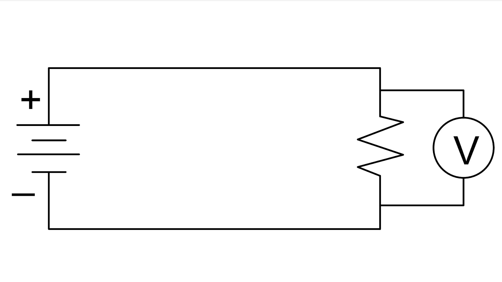
Voltmeter In Circuit. It is represented by the alphabet v inside. the voltmeter indicates polarity by direction of needle direction (analog) or sign of numerical indication (digital). Voltmeters work by connecting in parallel to the circuit, using high resistance to measure voltage. a voltmeter is an instrument that measures the difference in electrical potential between two points in an electric circuit. to get an effective voltmeter meter range in excess of 1/2 volt, we’ll need to design a circuit allowing only a precise proportion of measured. a voltmeter is an instrument used for measuring electric potential difference between two points in an electric circuit. working principle of voltmeter: the instrument which measures the voltage or potential in volts is known as the voltmeter. Learn about the voltmeter types, symbol, uses and more. When the red test lead is positive (+) and. a voltmeter, also known as a voltage meter, is an instrument that measures the voltage or potential difference between two points of an electronic or electrical circuit.
from wiringfixbeyer.z13..core.windows.net
Learn about the voltmeter types, symbol, uses and more. a voltmeter is an instrument that measures the difference in electrical potential between two points in an electric circuit. a voltmeter is an instrument used for measuring electric potential difference between two points in an electric circuit. Voltmeters work by connecting in parallel to the circuit, using high resistance to measure voltage. a voltmeter, also known as a voltage meter, is an instrument that measures the voltage or potential difference between two points of an electronic or electrical circuit. working principle of voltmeter: the instrument which measures the voltage or potential in volts is known as the voltmeter. the voltmeter indicates polarity by direction of needle direction (analog) or sign of numerical indication (digital). to get an effective voltmeter meter range in excess of 1/2 volt, we’ll need to design a circuit allowing only a precise proportion of measured. When the red test lead is positive (+) and.
How Is A Voltmeter Connected In A Circuit
Voltmeter In Circuit Learn about the voltmeter types, symbol, uses and more. It is represented by the alphabet v inside. to get an effective voltmeter meter range in excess of 1/2 volt, we’ll need to design a circuit allowing only a precise proportion of measured. Voltmeters work by connecting in parallel to the circuit, using high resistance to measure voltage. the voltmeter indicates polarity by direction of needle direction (analog) or sign of numerical indication (digital). the instrument which measures the voltage or potential in volts is known as the voltmeter. Learn about the voltmeter types, symbol, uses and more. a voltmeter is an instrument that measures the difference in electrical potential between two points in an electric circuit. a voltmeter is an instrument used for measuring electric potential difference between two points in an electric circuit. When the red test lead is positive (+) and. working principle of voltmeter: a voltmeter, also known as a voltage meter, is an instrument that measures the voltage or potential difference between two points of an electronic or electrical circuit.